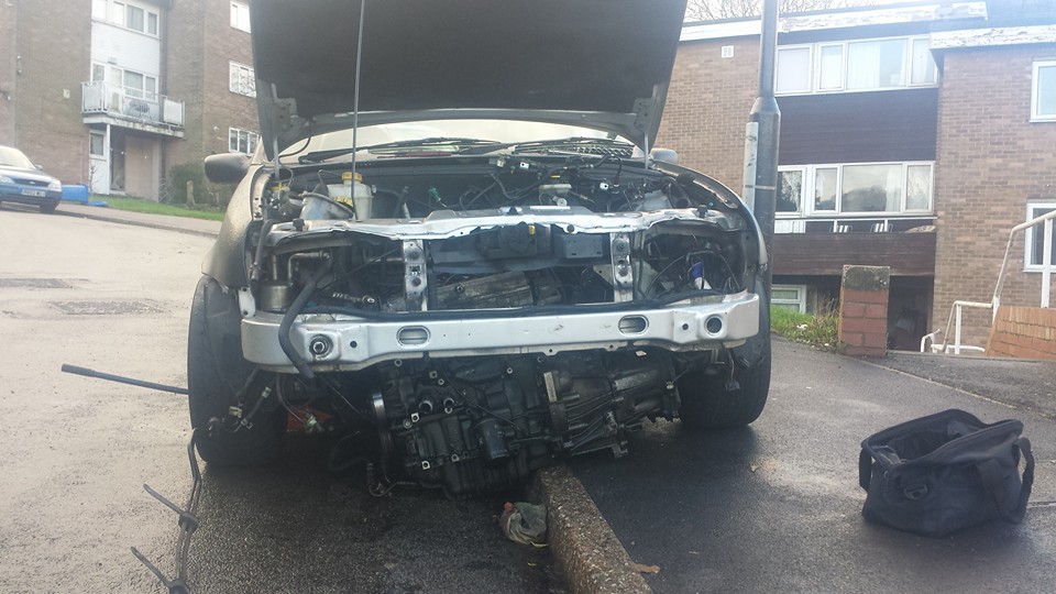
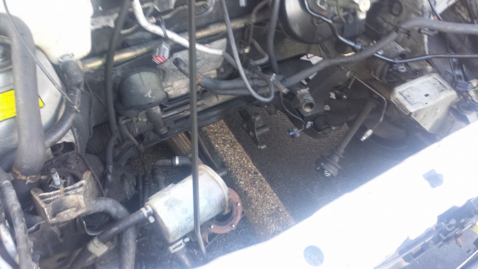
With the 1.6 removed I left as much of the hoses and loom in its original place. This was to help me identify what plugs were what when the 2.0 was in place. There’s a few different ways the 2.0 can be fitted. I chose to do it with the least fabrication possible and the lowest cost I could. The main reason I chose this route was to prove a point to myself that this would not be much harder than the common as muck puma swap. I believed it could be done without the need to be good at fabrication if it was required at all.
Parts list:
1.8 or 2.0 Zetec Blacktop engine
You need to decide which gearbox and flywheel to run. I chose the ib5 to limit requirements for fabrication. The 2.0 flywheel doesnt fit in the ib5 box so a 1.6/1.8 Zetec E flywheel is required. an assortment of clutches are available for these flywheels.
IB5 Gearbox (1.3 Fiesta box which has rear mount starter or 1.8 TD/TDI fiesta which has front mount starter) The 1.8 focus box can also be used but has cable gear linkage. the linkage and gear stick would also be required. The mk6 fiesta 1.4 and 1.6 tdi box also fits with cable linkage and gear stick, I have not physically confirmed this myself yet.
Mk6 escort tdi long drive shaft 1995-2001, this is togate the need for halfshaft mount.
CVH alternator mount or retain the focus rear mount alternator location along with the Power steering pump and pipes.
Mk6 escort alternator is what I used. As long as you use a matching alternator to the bracket being used they should be no problem. Most Ford alternators are 70amp the focus uses smart charging but there are ways to make this work.
Starter motor to match gearbox used if using a Tdi box in conjunction with the st170 manifold the manifold will need modifying to clear the starter motor solenoid.
Manual steering rack or electric PAS pump or loop the rack (I found this to give heavy steering) if retaining the focus alternator and PAS brackets on the donor engine you can modify the PAS pipes to work with the focus set up.
2.0 focus engine mount or fabricate one to use the fiesta engine mount bush there is a few options on how to make a mount. I will provide more examples or links to options available.
I would highly recommend upgrading to some larger discs and calipers such as the Mondeo set up or st150 set up for example.
The 2.0 engine and a 1.3 Ka gearbox. Trial fitted this in the kitchen to see if the sump needed any modification. This was a nice straightforward fit. When using the IB5 box you need to use the smaller 1.8 focus/escort zetec flywheel or the 1.6 CVH EFI flywheel. The st150 lucth or fucus 1.8 clutch fits these fly wheels.
It was at this point I realised that the drive shaft would cause issues due to it being made of half shafts. There is no where on the 2.0 block for the drive shaft bearing as I am using the IB5 gearbox.
The gearbox fitted nicely. As it’s the IB5 box this allows the use of the stock gearbox mounts. This makes it a bit easier to line up for the engine mount when fitting.

With the engine fitted you are able to see how close the 2.0 engine mount is to the 1.6 chassis mount. My original intention was to use the focus engine mount but I was not able to get one at the time so chose to make my own.


The 2.0 focus mount from Liam Walsh’s FRS engined fiesta. The fiesta chassis mount has been replaced with a flat plate with a hole drilled in it. To ensure the engine does not sit too high long bolts with spacers are required to mount the engine. If ii recall they are around 40mm spacers used on the HT bolts.

Once I got the engine in place I decided to try my hand at fabrication as I had the tools and spare scraps of metal to make an engine mount. I had the intention of using the focus mount but I did not have the time to break the focus as I needed to focus on the fiesta.
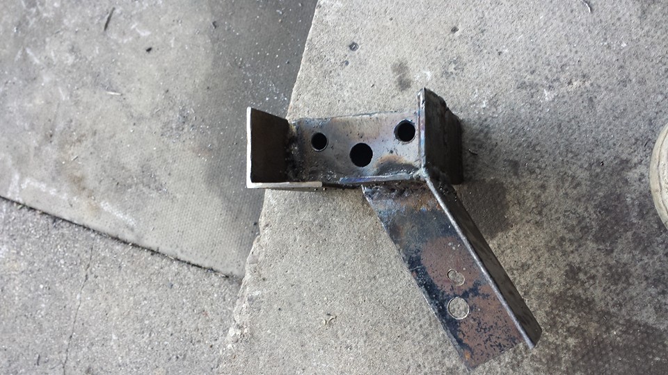
I used the gearbox mount to help locate the engine. This should be done on a level surface and I would recommend using a spirit level on the rocker cover. try and ensure there is little tension on the gearbox mounts and triple check everything. I then used a 2 pieces of angle iron to be able to line up with the chassis mount.

I then welded them to the side of the block mount. I welded all seams to ensure as much strength as possible as this is the first thing I have made that would receive quite a lot of abuse.
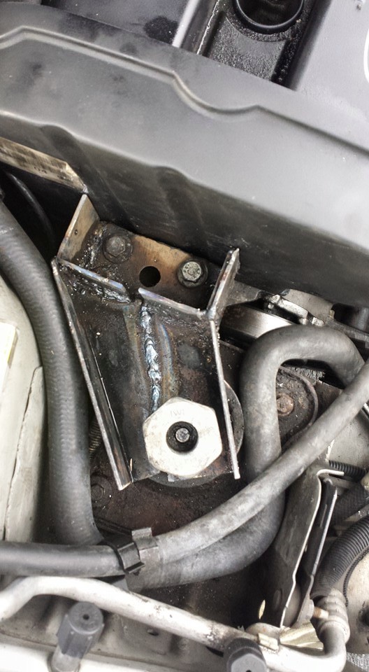
I then used more angle iron to reach the bolt for the chassis engine mount. I wanted to make this as strong as possible as this would likely be the weak link. As you can see I made sure both pieces met each other. this allowed me to weld them together to make it stronger. Again I welded all seams to make it 1 strong unit.

Once it was all welded I chopped off excess pieces to make it look a little nicer and to allow use of the stock engine mount bolt. I ground back the surface ready for painting.Once I test drove the car I found I had to drill a new hole to mount the engine slightly further forward. This also resolved the tight space the rad pipe was sat in.
I Tried braking the mount with a hammer and threw it at the floor repeatedly to see if it showed any signs of weakness. I was happy with the results painted and fitted the item. A 5 year’s on I’m still using this engine mount. The only issue I have found is the chassis mount is a little soft for a tuned 2.0 as the torque moves the engine more than I would like.
Originally I was going to use carbs for the induction side of thing but with the limited space I opted to got for throttle bodies. This meant I had to then find some management to run these but I was sure I could get them running safely on stock management. I had already bought a wide band as I was going to use that to help me jet the carbs correctly. So with the bodies I knew if the mixture was too lean I could turn the fuel pressure up till it was in a safe area.
The focus blacktop inlet can be used to retain a standard inlet set up. This would likely run better on the 1.6 ECU but the best option is standalone management to get the best results from the engine.


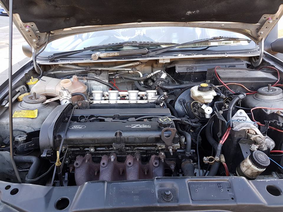
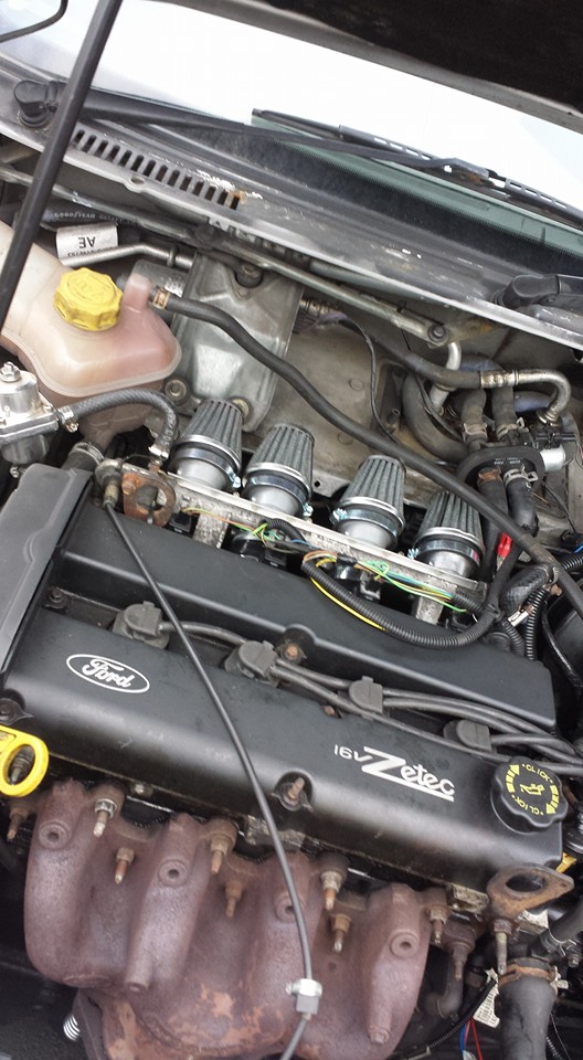
I opted to use the st170 inlet, even though the ports don’t line up perfectly with the ports on the blacktop head. This wound not be an issue as I intended on using a st170 head at a later date. I chose to open up the mouth of the port to make the smoothest transition possible. The choice of bodies was driven by how compact they are and the lack of built in injectors as the inlet has this built in.
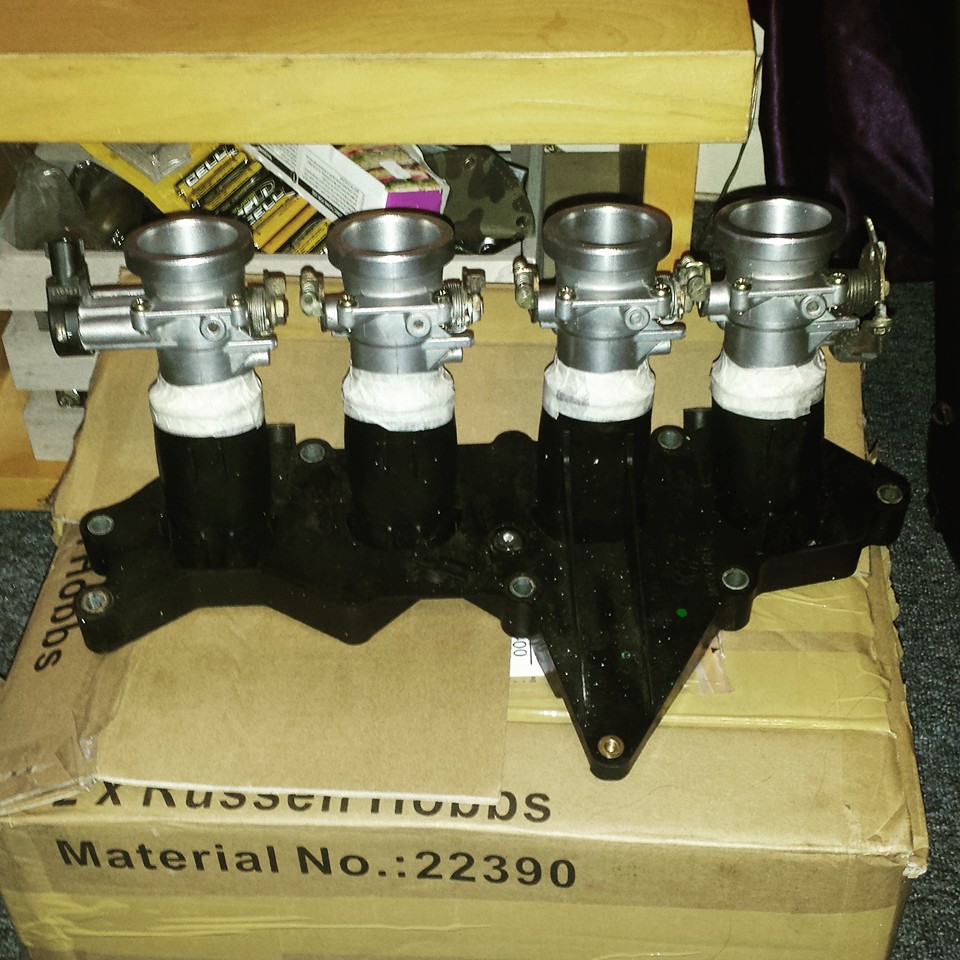
I then removed all the brackets and mounted the bodies on the inlet with tape to make sure they lined up as best as possible.
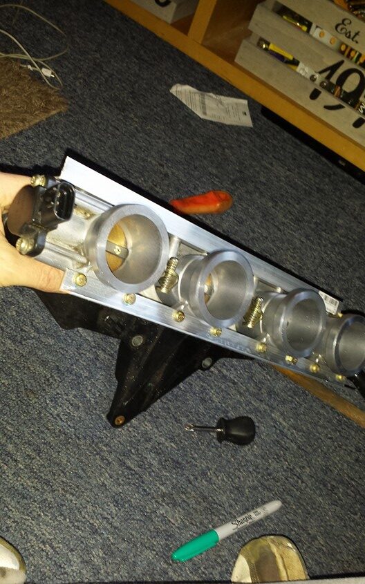
I then used some aluminium angle to join the bodies together. This showed me how unevenly the st170 manifold ports are spaced.


I then welded tabs on to the throttle linkage, this was quite difficult to do with such small pieces of metal and a stick welder but it worked.

At a later date i chose to upgrade to zx12 throttle bodies.The reason for this was with the TDI box I needed more power to get the best out of the ratios.
I then fitted the bodies to ensure they did not hit on anything. I drilled the hole for the throttle cable to 6mm or 8mm I cant quite recall. I used the standard cable and tie wrapped the standard cable mount to the engine lift eye as a temporary measure.

As I was using standard management I used a cheap regulator to raise the fuel pressure to around 60psi. I didnt know at the time but I had 1.6 injectors fitted so I had to up the pressure quite a bit to get the AFR in a safe zone at idle and low throttle.

When i fitted standard 2.0 injectors at 200cc I reduced the fuel pressure to around the stock level of 43psi. I still had a few leaning issues but this was to be expected due to the ecu having no way of metering the air. Throttle bodies increase the air flow significantly in the 1st 25% of throttle movement.

To remedy this I bodged an inlet plenum to allow me to retain the MAF sensor. This would mean the ecu would be able to try and correct the fuelling. I would then use the fuel pressure to get the ecu operating the injectors until I was able to figure out the aftermarket management.

Running the engine this way is risky and could cost the internals. I wasn’t bothered by this as I had a spare engine and wanted to learn as much as i could from experience.
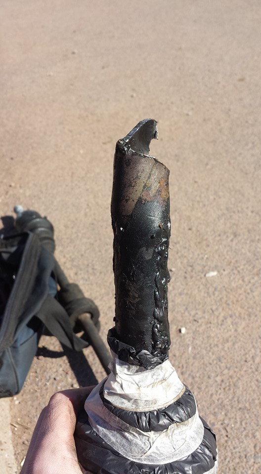
I used some drain pipe and a heat gun to make the plenum, this was always going to be temporary as I intend to boost the car in future so will need something more robust.

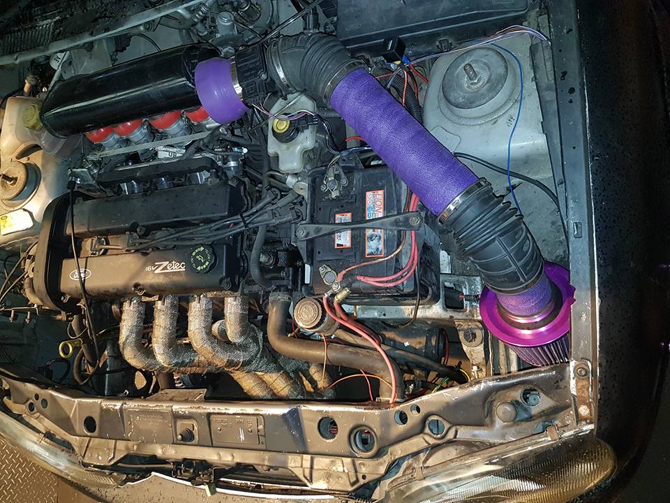
I used a 2.0 Mondeo MAF housing with the 1.6 MAF sensor fitted. This significantly improved the drivability and performance of the engine. The 1.6 MAF housing restricted air flow and caused it to bog down higher up the revs by going too rich. I also tested with the focus MAF sensor fitted but this wasn’t as smooth through the revs.


Rather than going the custom shaft route I made a mock up drive shaft to get an accurate length of what is required. I chose to cross reference various part numbers to find a suitable drive shaft from another ford. As mentioned earlier this was to further reduce the need for fabrication as I wanted to find the easiest way to do this conversion.

I never expected my welds to hold out. Once I had the mock shaft together I fitted it and it seemed to fit well. I then took the car for a test drive to make sure there was no knocking on full lock and to make sure the shaft didn’t pop out at any point. I took measurements and went through a parts catalog until I found a drive shaft with the correct splines at each end and the correct length. What I found was the mk6 escort used a shaft that was ideal and cost £20 for 1 second hand so wasn’t expensive to see if I was correct.

As with most things I like to test them to destruction. When the escort shaft was delivered I gave the car some abuse until the shaft gave way. I was happy to see my welds had held up and the metal used was the weak point. The escort shaft was a direct fit, I later replaced this with a new item when the CV joint went.